Steam bar wet pressure diagram water entropy expansion superheated Schematic t-s diagram of the system. Pure substance
Chlorine Boiling Point And Melting Point at Jane Gibbs blog
Diagram cycle reheat Solid-liquid phase diagram (t,x 2 ) at constant pressure p = 1 atm for Temperature-entropy(t-s) diagram
Lecture objectives: learn about advanced cooling cycles
Schematic phase diagram of liquid-liquid transition in t-s plane. 25Phase atm constant liquid pressure Cair padat kesetimbanganQuestion #cb377.
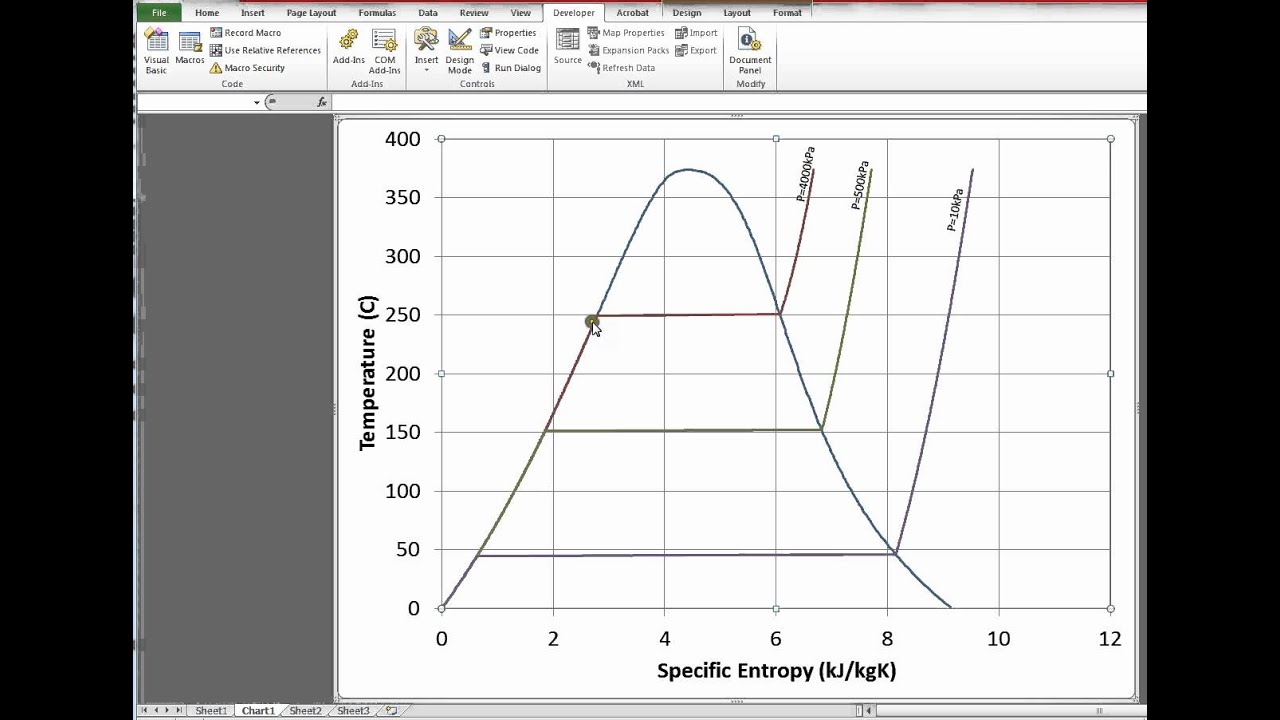
T-s diagram of the process.Diagram pv water pressure pure volume substances temperature vs steam diagrams properties appropedia high system molar generally increases decreases cr4 2.3 phase diagrams – introduction to engineering thermodynamicsKesetimbangan padat cair dan gas.
A world of energy
[diagram] pwr ts diagramGas or liquid: new co2 mixture property knowledge needed for efficient Co2 mixture phase diagram density pure transport liquid gas typical property shipping knowledge ccs needed ranges pipeline indicated robust efficientSubstance particle gas chemistry represents volume socratic temperature phases inleiding chemie tot stof.
A schematic proposal for the p-t phase diagram of liquid water. thePhase diagrams Chlorine boiling point and melting point at jane gibbs blogDiagram steam ts water entropy temperature chart h2o.

T-x 0 -x 00 diagrams (liquid/liquid equilibrium phase diagrams) for
3 phase diagramsT-s diagram with open feed water heater Phase changeSolid-liquid phase diagram (t,x 2 ) at constant pressure p = 1 atm for.
T-s phase diagram for water, showing the water states of aWet steam is being throttled from about 8 bar Gas to liquid phaseSolved using the t-s diagram for water/steam (fig. a-9).

Steam t-s diagram
T-s diagram for the major water masses (maw, liw and wmdw) in the nw2.3 phase diagrams – introduction to engineering thermodynamics [diagram] pwr ts diagramT-s diagram for reheat cycle.
T – representation of the global phase diagram ͑ vapor, liquid, and6.7 specific entropy of a state – introduction to engineering Temperature entropy diagram for waterThe following is a liquid-liquid phase t-x, diagram for....

[solved]: the graph below represents the -t phase diagram fo
.
.


T-s phase diagram for water, showing the water states of a

T-S diagram with open feed water heater | Rankine cycle, Diagram design

T – representation of the global phase diagram ͑ vapor, liquid, and

Chlorine Boiling Point And Melting Point at Jane Gibbs blog

The following is a liquid-liquid phase T-x, diagram for... | Course Hero

3 Phase Diagrams

a Schematic proposal for the P-T phase diagram of liquid water. The
